Introduction
CNC machining, also called CNC manufacturing, is a new high precision computer-controlled manufacturing. CNC machines basically take instructions from the program written on the computer to manipulate the cutting tools. In this post, we will share some information on CNC machining processes.
Due to the control of the computer, its precision in cutting material is extremely accurate. CNC machines can rotate tools around various axis usually 3 to 5. Axis is referred to as the degree of freedom a tool can move. 3-axis CNC machines are defined as Cartesian coordinates i.e., X, Y and Z axis. However, in the case of 5-axis there are two more possibilities of tool rotation. In a 5-axis CNC machining system the tool can move in rotation along the X and Y axis while moving in one direction that could be either of X, Y or Z. In comparison to manual manufacturing processes like lathe and milling machines, CNC machining is much faster, reliable, safe and precise.
General idea of CNC Machining Processes
CNC Machining is a subtractive process, which means it removes material to create the required shape or product from a stock piece of material. The material used for this manufacturing process can be of a material such as Steel, Aluminum and Titanium, etc. The output part or product has high surface finishing with great tolerances and fits. CNC machining process can be divided into the following 4 steps:
1. Create Computer Aided Design (CAD) Model
CNC machines cutting action of material is controlled by using computer-controlled commands. Like the tool that cuts the material moves in a defined axis at a controlled speed. Thus, it means that before implementing commands in the computer to control the direction and axis of rotation of the tool, first, we need a geometry modeled within the computer. The computer-aided design tools allow the user to define the shape of the end product virtually and implement any assembly of other tools with the part he is manufacturing. That is how he can predict whether the mechanism he is created will be feasible or not. There is plenty of software out there such as Autodesk Fusion 360, PTC CREO, CATIA and SOLIDWORKS that allows you to develop expected models of required parts or products easily.
2. Converting CAD Model into Geometry Code
Once an Engineer or a concerned person creates a model of the required product or part in a Computer-Aided Design (CAD) modeling software. Then the final CAD model is converted into G-Code. The G-Code is indicated as a general or a geometric code that contains the set of instructions to control CNC machine cutting tool movements. This G-code is a set of instructions that contains the axis information in the form of positive and negative decimal numbers. This code is also considered as a set of commands that instruct the cutting tool of the CNC Machine to move in a specified axis at a given speed.
In addition to G-Code, there is another code called M-Code, which is called Miscellaneous Function. M-Code basically controls the auxiliary functions of the CNC machine. Those functions include the programmable logic control (PLC) of the CNC machine. We can more simply define M-Code as it controls the start and stops functionality of the CNC machine. The major function of M-Code is to control non-cutting actions of CNC machines like controlling coolants flooding to keep the temperature of tool low and remove the scraps from the cutting position. One other major difference between G-Code and M-Code is G-Code is changed at every new manufacturing process of stock material, where M-Code remains the same for all the manufacturing processes carried out by CNC machines.
This information is passed to CNC machines to manufacture the desired product and that is called Computer-aided manufacturing (CAM). That means the CNC machine will work and move the cutting tool in a defined axis with incredibly high accuracy.
3. Insert program in Computer Numeric Control (CNC) Machine
To enable the CNC machine to work according to G-code, first, it is needed to put or upload the G-code in the CNC machine. Hence, we first set the other parameters such as choosing the required toolset, starting the coolant and setting the speed of the spindle for rotation. Now the launch is almost complete. All you need is to browse the G-Code file that has generally .nc extension and then press open or upload from your CNC machine. Generally, the movement of the cutting tool starts as soon as we run the file.
4. CNC Machining Process Implementation
Due to the precise movement of the cutting tool in prescribed or instructed from G-code, the end results have high-end finishing results. Thus, its preciseness is generally measured in thousands of an inch. We can also categorize the CNC machining process depending upon the tolerances we need in our finished product. For example, if the tolerance of the end material is around ± 0.005 in; then we can consider it as Standard Machining. If this tolerance allowance is reduced to around ± 0.001 in; then we can say that it is Fine Machining. However, this tolerance can reduce further such as for polishing purposes. That requires very tight tolerances such as ± 0.0005 in and such machining level is considered as Specialized CNC Machining process. The control of axis rotation is carried by motors. The motor could be either a stepper or servo motor. The difference between stepper and server motor is that stepper moves between steps and servo rotates in degree angles. Mostly, servo motors are deployed in CNC machines because of their high precision and running faster than stepper motors. In addition to that servo motors provide constant torque across the operation while maintaining the speed of the cutting tool. The life of the cutting tool primarily depends on this parameter.
CNC Machining Operations
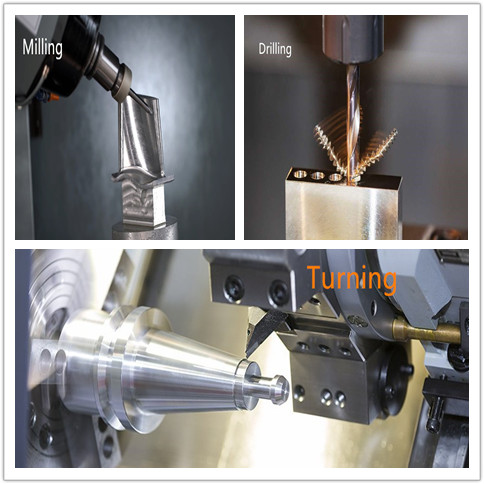
CNC Machining operations involve the three most basic steps of removing materials from stocks. Those three operations are Lathes, Milling and Drilling. CNC machining involves the working of all these operations at once to make the desired product with very high-end finishing results.
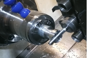
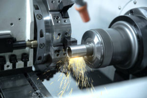
In the lathe machining process, the material is removed by the movement of stock material in only a single direction. It means that the product revolves around its axis meanwhile the cutting remains stationary at its defined position. The lathe machining process is also considered as a turning process as in this process the workpiece rotates, and a profile is created on the workpiece when it comes in contact with a stationary tool. The feed is also given to the manufacturing part to move in a defined direction. The profiles generated while doing this operation are generally round or cylindrical in shape in the CNC machining process.
However, the working of the milling process is quite opposite to lathe, which includes the rotation of tools instead of the material that is under operation. This gives more flexibility in the creation of any profile on the workpiece we employ in CNC machining. As the tool moves in any direction while rotating around its axis the feed is also given in workpiece direction as a result a variety of shapes are achieved by performing this operation in a CNC milling machine.
In addition to these two processes, the third operation is drilling that is used to create holes in the stock material at defined positions at precise lengths. The drilling process may require multiple size holes therefore multiple drill bits are employed at the same time by just replacing the drill bit fixed in the tool post in the CNC machine. The selection of drill bit of hole is also done by the code employed in CNC Machine. By using the drilling process, a cylindrical hole can be created at a perpendicular position as well as at an angular position.
As we can imagine, the CNC machining can be done on different materials, but can we use the same cutting tools for all the types of materials of stock pieces? No, we cannot use the same cutting material for all the jobs! We need to decide the tool material for cutting different stock pieces as well as we need to decide the rpm of tool rotation depending upon the hardness of a material.
The size of the CNC machine depends upon its usage. This means we first need to know what kind of products we are going to manufacture. Also, the travel of the tool in any axis depends upon the material of the tool and raw materials. Thus, the part dimensions are needed to decide the required tooling and determine the travel limitation of the cutting tool. Generally, the dimension of the CNC machine could be around 80×30×40 inches. However, the size varies a lot depending upon the application of it and the size of the manufacturing material we are deploying in it.
CNC Machine Cutting Tool
Since we know CNC machining is a subtractive process. That means the material is removed from the piece of the block to create the required shape or profile on it. Therefore, a cutting tool must be needed stronger than the piece of block that we need to manufacture. Even the cutting tool is not of the same material throughout its length. The tip of the cutting tool is sometimes different from the body. As the head of a cutting tool goes inside the spindle of the CNC machine therefore it does not come in contact with processing material. In addition to that, there are helical shapes on the whole body of the cutting tool. This shape of the cutting tool gives the advantage while the drilling process. As the material is removed while drilling it needs space to remove the scrap from the cutting path. Thus, the helical shape on the cutting tool allows the material to move out of the hole as a scrap.
Common types of materials used for cutting material are given below:
Carbon Steel
Carbon steel is a cheap material and widely available. It contains 0.6 to 1.5 percent carbon along with the minute quantity of other materials such as manganese and silicon etc.
High-Speed Steel (HSS)
HSS is a stronger material than carbon steel and it is used for cutting more hard materials. It is more resilient because it is a mixture of tungsten and chromium.
Carbide
Carbide is even more resilient than HSS. It has good heat resistance which means it does not get hot easily when it comes in contact with a piece of material it cuts. Its hardness comes from the carbide particles used to make this tool.
Ceramics
Sometimes we need to cut soft material such as aluminum that does not require a very hard or strong cutting tool. Thus, they are used in such instances to cut material as ceramics-based cutting tools have low manufacturing costs as well as highly corrosion and heat resistant.
In addition to a selection of cutting material types, we also need to make the coating of other materials on an actual tool to increase its life. These coatings of different materials enhance the properties of the cutting tool. This makes the cutting tool more reliable and long life. A few types of coatings are mentioned as Titanium Nitride (TiN), Titanium Carbon Nitride (TiCN), Chromium Nitride (CrN) and Diamond tip.
Conclusion
CNC machining is a high-precision manufacturing process. It requires a set of instructions as commands to move the cutting tool in the prescribed axis. This set of instructions is known as G-Code. This G-Code can be created from the part model designed in a computer known as a CAD file. Thus, the shape of the desired product is first designed on the computer by using some modeling software. Then the part geometry is converted to G-code which is generally in the form of .nc extension. This file is uploaded to the CNC machine to define the path of the cutting tool throughout the operation of creating desired high finishing product. The cutting tool rotation and feed are generally controlled by servo motors that rotate in-degree angles.
The CNC machine can be of 3 or 5-axis depending upon the need of applications. The axes are referred to the degrees of freedom a cutting tool can move. The operation of CNC machines is highly precise. The tolerance of the finished product can go up to 0.0001 inches or even more. CNC machining is basically a combination of three processes which are turning, milling and drilling. Depending upon the profile of we want to manufacture on the stock material one of these operations is performed. The cutting material is also used in different shapes and materials depending upon the type of stock material and profile needed.


